Overview
Flanges are very commonly used metal products. If you are engaged in the metal material industry, you must have some concept of it. However, faced with a variety of flange types and different pressure rating classes, you may still lack some clear understanding of it.
In addition, the size representation method of flanges is also very complicated, which often makes people confused.
In this article, we will introduce in detail what flanges are, their functions, their classification, and how to convert their sizes. I hope it can help you have a deeper understanding of this material.
What is Flange?
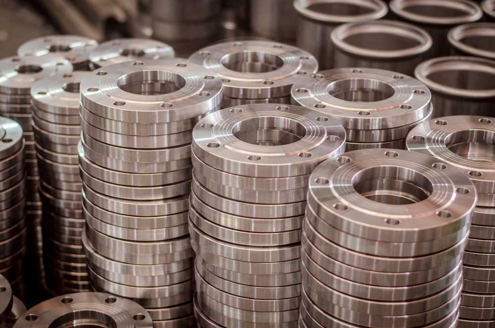
A flange is a disc-shaped part. Its function is to connect two pipes. The following pictures show what typical flanges look like:
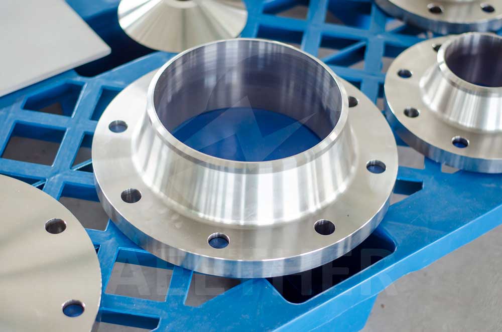
There is a relatively large hole in the middle of the flange, called the bore, whose size is close to the inner diameter of the pipe and is where the fluid passes.

The outside of the large hole is an annular surface, called the flange face, which is the contact surface after the two flanges are connected and determines the sealing of the flange. The following picture shows some common flange faces:

There is a circle of evenly arranged small holes close to the edge of the flange. These small holes are called bolt holes and are used to connect flanges.

Flange Connection Method
In order to connect two pipes together, two flanges are required to be connected to the pipe ends of the two pipes respectively. The flange and the pipe can be connected by threading or welding.

After the flange and the pipe are connected, a gasket is inserted between the two flanges, which is used to seal the flange connection. The flanges are connected by bolts and nuts. Each bolt hole of the flange needs to be fixed with bolts to ensure that the flange connection is tight enough.

Classification of Flanges
According to the different connection methods and functions between flanges and pipelines, flanges are divided into different types, namely: threaded flange (TH), slip-on welding flange (SO), blind flange (BL), socket welding flange (SW), welding neck flange (WN) and lapped flange (LJ). Below we will introduce them one by one:
Threaded (TH) Flange
A threaded flange, as the name implies, is a flange with threads. It is connected to the pipeline by threads. Therefore, the pipe end of the pipeline also needs to be processed with matching threads:

The advantage of threaded flange is that it is easy to install, but its pressure bearing capacity is relatively general.
Slip-on Welding (SO) Flange
Slip-on welding flange refers to the flange connected between the pipeline and the flange by flat welding. Its welding diagram is as follows:

The welding of slip-on welding flange is relatively easy. At the same time, flat welding does not require beveling at the pipe end. However, its pressure bearing capacity is relatively limited.
Blind (BL) Flange
A blind flange is a flange without a bore. Its main function is to close the pipe end:

Socket Welding (SW) Flange
A socket welding flange refers to a flange connected to the pipeline by socket welding. This connection method is the most complicated, but it has the best pressure bearing capacity.

Welding Neck (WN) Flange
The welding neck flange is the most commonly used flange, which is connected to the pipe by butt welding. The welding neck flange requires bevels on both ends of the pipe. This connection method is simpler than socket welding, but it also has a very good pressure bearing capacity.

Lapped (LJ) Flange
The lapped flange is a movable flange. It nests the part where the flange is connected to the pipe and the connecting part between the flanges. Therefore, after the connection, there is still a certain amount of movable space between the pipe and the flange, which makes it more resistant to deformation, but sacrifices a certain degree of pressure resistance.
Pressure Rating Class of Flanges
Depending on the different pressure bearing capacity requirements, each type of flange corresponds to different pressure rating classes. The pressure rating class is indicated by # or Class, which represents how many pounds of pressure it can withstand. Common pressure ratings are:
Even for the same type of flange, different pressure rating classes correspond to different sizes. Therefore, we should consider every piece of information about the flange to determine its final size. Let's continue to introduce how to correctly indicate the size of the flange.
How to Express Flange Size?
The standard way to express flange size is:
This expression is not intuitive. Therefore, we need to analyze each parameter one by one.
2" SCH40 represents the size of the pipe connected to the flange. The larger the pipe size, the larger the flange size. If you have read our previous article, you will know that this is a Nominal Pipe Schedule. It can well represent the standard size of the pipe. If you are not familiar with this, we recommend you to read our previous article on Nominal Pipe Schedule:

300# represents the pressure rating class of the flange. The higher the pressure rating class, the higher the pressure the flange can withstand and the larger the size of the flange.
RF represents the falge face, which has no effect on the size of the flange itself.
The above are all written expressions of flange size. Even if its parameters are explained one by one, you may still find it difficult to have a clear concept. For this reason, we must express the size of the flange more intuitively. So the following drawing shows the dimensions of each flange type clearly:

In summary, O represents the outer diameter of the flange, tf represents the thickness of the flange, B represents the diameter of bore of the flange, and X represents the diameter of the connection between flange and pipe. Y represents the total height of the flange. Other parameters only exist in certain types of flanges, and they are clearly shown in the drawing.
Conversion of Flange Size
Now that we know the written and drawing representations of flanges, we only need to know how to convert them.
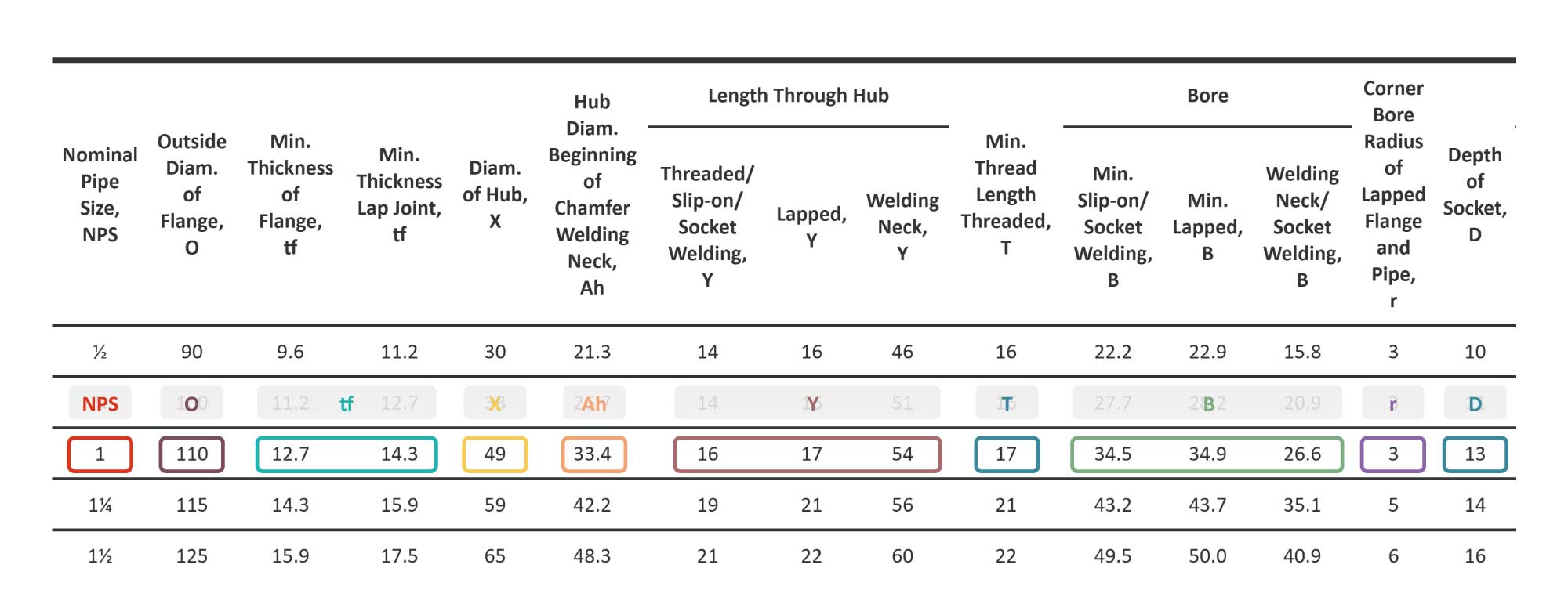
The conversion methods of flange sizes are defined in different tables of ASME B16.5. We need to combine the flange type, pressure rating class and Nominal Pipe Schedule to convert the written representation method into the drawing representation method. Here is the comparison table for 150#:
| Nominal Pipe Size, NPS |
Outside Diam. of Flange, O |
Min. Thickness of Flange, tf |
Min. Thickness Lap Joint, tf |
Diam. of Hub, X |
Hub Diam. Beginning of Chamfer Welding Neck, Ah |
Length Through Hub | Min. Thread Length Threaded, T |
Bore | Corner Bore Radius of Lapped Flange and Pipe, r |
Depth of Socket, D |
|||||
|---|---|---|---|---|---|---|---|---|---|---|---|---|---|---|---|
| Threaded/ Slip-on/ Socket Welding, Y |
Lapped, Y |
Welding Neck, Y |
Min. Slip-on/ Socket Welding, B |
Min. Lapped, B |
Welding Neck/ Socket Welding, B |
||||||||||
| ½ | 90 | 9.6 | 11.2 | 30 | 21.3 | 14 | 16 | 46 | 16 | 22.2 | 22.9 | 15.8 | 3 | 10 | |
| ¾ | 100 | 11.2 | 12.7 | 38 | 26.7 | 14 | 16 | 51 | 16 | 27.7 | 28.2 | 20.9 | 3 | 11 | |
| 1 | 110 | 12.7 | 14.3 | 49 | 33.4 | 16 | 17 | 54 | 17 | 34.5 | 34.9 | 26.6 | 3 | 13 | |
| 1¼ | 115 | 14.3 | 15.9 | 59 | 42.2 | 19 | 21 | 56 | 21 | 43.2 | 43.7 | 35.1 | 5 | 14 | |
| 1½ | 125 | 15.9 | 17.5 | 65 | 48.3 | 21 | 22 | 60 | 22 | 49.5 | 50.0 | 40.9 | 6 | 16 | |
| 2 | 150 | 17.5 | 19.1 | 78 | 60.3 | 24 | 25 | 62 | 25 | 61.9 | 62.5 | 52.5 | 8 | 17 | |
| 2½ | 180 | 20.7 | 22.3 | 90 | 73.0 | 27 | 29 | 68 | 29 | 74.6 | 75.4 | 62.7 | 8 | 19 | |
| 3 | 190 | 22.3 | 23.9 | 108 | 88.9 | 29 | 30 | 68 | 30 | 90.7 | 91.4 | 77.9 | 10 | 21 | |
| 3½ | 215 | 22.3 | 23.9 | 122 | 101.6 | 30 | 32 | 70 | 32 | 103.4 | 104.1 | 90.1 | 10 | ... | |
| 4 | 230 | 22.3 | 23.9 | 135 | 114.3 | 32 | 33 | 75 | 33 | 116.1 | 116.8 | 102.3 | 11 | ... | |
| 5 | 255 | 22.3 | 23.9 | 164 | 141.3 | 35 | 36 | 87 | 36 | 143.8 | 144.4 | 128.2 | 11 | ... | |
| 6 | 280 | 23.9 | 25.4 | 192 | 168.3 | 38 | 40 | 87 | 40 | 170.7 | 171.4 | 154.1 | 13 | ... | |
| 8 | 345 | 27.0 | 28.6 | 246 | 219.1 | 43 | 44 | 100 | 44 | 221.5 | 222.2 | 202.7 | 13 | ... | |
| 10 | 405 | 28.6 | 30.2 | 305 | 273.0 | 48 | 49 | 100 | 49 | 276.2 | 277.4 | 254.6 | 13 | ... | |
| 12 | 485 | 30.2 | 31.8 | 365 | 323.8 | 54 | 56 | 113 | 56 | 327.0 | 328.2 | 304.8 | 13 | ... | |
| 14 | 535 | 33.4 | 35.0 | 400 | 355.6 | 56 | 79 | 125 | 57 | 359.2 | 360.2 | ... | 13 | ... | |
| 16 | 595 | 35.0 | 36.6 | 457 | 406.4 | 62 | 87 | 125 | 64 | 410.5 | 411.2 | ... | 13 | ... | |
| 18 | 635 | 38.1 | 39.7 | 505 | 457.0 | 67 | 97 | 138 | 68 | 461.8 | 462.3 | ... | 13 | ... | |
| 20 | 700 | 41.3 | 42.9 | 559 | 508.0 | 71 | 103 | 143 | 73 | 513.1 | 514.4 | ... | 13 | ... | |
| 24 | 815 | 46.1 | 47.7 | 663 | 610.0 | 81 | 111 | 151 | 83 | 616.0 | 616.0 | ... | 13 | ... | |
If your flange pressure level is 150#, you only need to look at this table. The first column of the table is the NPS value, which corresponds to the number in front of the symbol '"'. Now that you have determined the NPS, you only need to look at the corresponding row. Then, you can see that the different columns of this row represent different size parameters of different flanges.
If your flange pressure rating class is not 150#, then you need to find the table corresponding to the rating class you need. We have listed them one by one below:
| Nominal Pipe Size, NPS |
Outside Diam. of Flange, O |
Min. Thickness of Flange tf |
Min. Thickness Lap Joint, tf |
Diam. of Hub, X |
Hub Diam. Beginning of Chamfer Welding Neck, Ah |
Length Through Hub | Min. Thread Length Threaded, T |
Bore | Corner Bore Radius of Lapped Flange and Pipe, r |
Min. Counter- bore Threaded Flange, Q |
Depth of Socket, D |
|||||
|---|---|---|---|---|---|---|---|---|---|---|---|---|---|---|---|---|
| Threaded/ Slip-on/ Socket Welding, Y |
Lapped, Y |
Welding Neck, Y |
Min. Slip-on/ Socket Welding, B |
Min. Lapped, B |
Welding Neck/ Socket Welding, B |
|||||||||||
| ½ | 95 | 12.7 | 14.3 | 38 | 21.3 | 21 | 22 | 51 | 16 | 22.2 | 22.9 | 15.8 | 3 | 23.6 | 10 | |
| ¾ | 115 | 14.3 | 15.9 | 48 | 26.7 | 24 | 25 | 56 | 16 | 27.7 | 28.2 | 20.9 | 3 | 29.0 | 11 | |
| 1 | 125 | 15.9 | 17.5 | 54 | 33.4 | 25 | 27 | 60 | 18 | 34.5 | 34.9 | 26.6 | 3 | 35.8 | 13 | |
| 1¼ | 135 | 17.5 | 19.1 | 64 | 42.2 | 25 | 27 | 64 | 21 | 43.2 | 43.7 | 35.1 | 5 | 44.4 | 14 | |
| 1½ | 155 | 19.1 | 20.7 | 70 | 48.3 | 29 | 30 | 67 | 23 | 49.5 | 50.0 | 40.9 | 6 | 50.3 | 16 | |
| 2 | 165 | 20.7 | 22.3 | 84 | 60.3 | 32 | 33 | 68 | 29 | 61.9 | 62.5 | 52.5 | 8 | 63.5 | 17 | |
| 2½ | 190 | 23.9 | 25.4 | 100 | 73.0 | 37 | 38 | 75 | 32 | 74.6 | 75.4 | 62.7 | 8 | 76.2 | 19 | |
| 3 | 210 | 27.0 | 28.6 | 117 | 88.9 | 41 | 43 | 78 | 32 | 90.7 | 91.4 | 77.9 | 10 | 92.2 | 21 | |
| 3½ | 230 | 28.6 | 30.2 | 133 | 101.6 | 43 | 44 | 79 | 37 | 103.4 | 104.1 | 90.1 | 10 | 104.9 | ... | |
| 4 | 255 | 30.2 | 31.8 | 146 | 114.3 | 46 | 48 | 84 | 37 | 116.1 | 116.8 | 102.3 | 11 | 117.6 | ... | |
| 5 | 280 | 33.4 | 35.0 | 178 | 141.3 | 49 | 51 | 97 | 43 | 143.8 | 144.4 | 128.2 | 11 | 144.4 | ... | |
| 6 | 320 | 35.0 | 36.6 | 206 | 168.3 | 51 | 52 | 97 | 47 | 170.7 | 171.4 | 154.1 | 13 | 171.4 | ... | |
| 8 | 380 | 39.7 | 41.3 | 260 | 219.1 | 60 | 62 | 110 | 51 | 221.5 | 222.2 | 202.7 | 13 | 222.2 | ... | |
| 10 | 445 | 46.1 | 47.7 | 321 | 273.0 | 65 | 95 | 116 | 56 | 276.2 | 277.4 | 254.6 | 13 | 276.2 | ... | |
| 12 | 520 | 49.3 | 50.8 | 375 | 323.8 | 71 | 102 | 129 | 61 | 327.0 | 328.2 | 304.8 | 13 | 328.6 | ... | |
| 14 | 585 | 52.4 | 54.0 | 425 | 355.6 | 75 | 111 | 141 | 64 | 359.2 | 360.2 | ... | 13 | 360.4 | ... | |
| 16 | 650 | 55.6 | 57.2 | 483 | 406.4 | 81 | 121 | 144 | 69 | 410.5 | 411.2 | ... | 13 | 411.2 | ... | |
| 18 | 710 | 58.8 | 60.4 | 533 | 457.0 | 87 | 130 | 157 | 70 | 461.8 | 462.3 | ... | 13 | 462.0 | ... | |
| 20 | 775 | 62.0 | 63.5 | 587 | 508.0 | 94 | 140 | 160 | 74 | 513.1 | 514.4 | ... | 13 | 512.8 | ... | |
| 24 | 915 | 68.3 | 69.9 | 702 | 610.0 | 105 | 152 | 167 | 83 | 616.0 | 616.0 | ... | 13 | 614.4 | ... | |
| Nominal Pipe Size, NPS |
Outside Diam. of Flange, O |
Min. Thickness of Flange tf |
Diam. of Hub, X |
Hub Diam. Beginning of Chamfer Welding Neck, Ah |
Length Through Hub | Min. Thread Length Threaded, T |
Bore | Corner Bore Radius of Lapped Flange and Pipe, r |
Min. Counter- bore Threaded Flange, Q |
||||
|---|---|---|---|---|---|---|---|---|---|---|---|---|---|
| Threaded/ Slip-on/ Socket Welding, Y |
Lapped, Y |
Welding Neck, Y |
Min. Slip-on/ Socket Welding, B |
Min. Lapped, B |
Welding Neck/ Socket Welding, B |
||||||||
| ½ | 95 | 14.3 | 38 | 21.3 | 22 | 22 | 52 | 16 | 22.2 | 22.9 | ... | 3 | 23.6 |
| ¾ | 115 | 15.9 | 48 | 26.7 | 25 | 25 | 57 | 16 | 27.7 | 28.2 | ... | 3 | 29.0 |
| 1 | 125 | 17.5 | 54 | 33.4 | 27 | 27 | 62 | 18 | 34.5 | 34.9 | ... | 3 | 35.8 |
| 1¼ | 135 | 20.7 | 64 | 42.2 | 29 | 29 | 67 | 21 | 43.2 | 43.7 | ... | 5 | 44.4 |
| 1½ | 155 | 22.3 | 70 | 48.3 | 32 | 32 | 70 | 23 | 49.5 | 50.0 | ... | 6 | 50.6 |
| 2 | 165 | 25.4 | 84 | 60.3 | 37 | 37 | 73 | 29 | 61.9 | 62.5 | ... | 8 | 63.5 |
| 2½ | 190 | 28.6 | 100 | 73.0 | 41 | 41 | 79 | 32 | 74.6 | 75.4 | ... | 8 | 76.2 |
| 3 | 210 | 31.8 | 117 | 88.9 | 46 | 46 | 83 | 35 | 90.7 | 91.4 | ... | 10 | 92.2 |
| 3½ | 230 | 35.0 | 133 | 101.6 | 49 | 49 | 86 | 40 | 103.4 | 104.1 | ... | 10 | 104.9 |
| 4 | 255 | 35.0 | 146 | 114.3 | 51 | 51 | 89 | 37 | 116.1 | 116.8 | ... | 11 | 117.6 |
| 5 | 280 | 38.1 | 178 | 141.3 | 54 | 54 | 102 | 43 | 143.8 | 144.5 | ... | 11 | 144.4 |
| 6 | 320 | 41.3 | 206 | 168.3 | 57 | 57 | 103 | 46 | 170.7 | 171.4 | ... | 13 | 171.4 |
| 8 | 380 | 47.7 | 260 | 219.1 | 68 | 68 | 117 | 51 | 221.5 | 222.2 | ... | 13 | 222.2 |
| 10 | 445 | 54.0 | 321 | 273.0 | 73 | 102 | 124 | 56 | 276.2 | 277.4 | ... | 13 | 276.2 |
| 12 | 520 | 57.2 | 375 | 323.8 | 79 | 108 | 137 | 61 | 327.0 | 328.2 | ... | 13 | 328.6 |
| 14 | 585 | 60.4 | 425 | 355.6 | 84 | 117 | 149 | 64 | 359.2 | 360.2 | ... | 13 | 360.4 |
| 16 | 650 | 63.5 | 483 | 406.4 | 94 | 127 | 152 | 69 | 410.5 | 411.2 | ... | 13 | 411.2 |
| 18 | 710 | 66.7 | 533 | 457.0 | 98 | 137 | 165 | 70 | 461.8 | 462.3 | ... | 13 | 462.0 |
| 20 | 775 | 69.9 | 587 | 508.0 | 102 | 146 | 168 | 74 | 513.1 | 514.4 | ... | 13 | 512.8 |
| 24 | 915 | 76.2 | 702 | 610.0 | 114 | 159 | 175 | 83 | 616.0 | 616.0 | ... | 13 | 614.4 |
| Nominal Pipe Size, NPS |
Outside Diam. of Flange, O |
Min. Thickness of Flange tf |
Diam. of Hub, X |
Hub Diam. Beginning of Chamfer Welding Neck, Ah |
Length Through Hub | Min. Thread Length Threaded, T |
Bore | Corner Bore Radius of Lapped Flange and Pipe, r |
Min. Counter- bore Threaded Flange, Q |
Depth of Socket, D |
||||
|---|---|---|---|---|---|---|---|---|---|---|---|---|---|---|
| Threaded/ Slip-on/ Socket Welding, Y |
Lapped, Y |
Welding Neck, Y |
Min. Slip-on/ Socket Welding, B |
Min. Lapped, B |
Welding Neck/ Socket Welding, B |
|||||||||
| ½ | 95 | 14.3 | 38 | 21.3 | 22 | 22 | 52 | 16 | 22.2 | 22.9 | ... | 3 | 23.6 | 10 |
| ¾ | 115 | 15.9 | 48 | 26.7 | 25 | 25 | 57 | 16 | 27.7 | 28.2 | ... | 3 | 29.0 | 11 |
| 1 | 125 | 17.5 | 54 | 33.4 | 27 | 27 | 62 | 18 | 34.5 | 34.9 | ... | 3 | 35.8 | 13 |
| 1¼ | 135 | 20.7 | 64 | 42.2 | 29 | 29 | 67 | 21 | 43.2 | 43.7 | ... | 5 | 44.4 | 14 |
| 1½ | 155 | 22.3 | 70 | 48.3 | 32 | 32 | 70 | 23 | 49.5 | 50.0 | ... | 6 | 50.6 | 16 |
| 2 | 165 | 25.4 | 84 | 60.3 | 37 | 37 | 73 | 29 | 61.9 | 62.5 | ... | 8 | 63.5 | 17 |
| 2½ | 190 | 28.6 | 100 | 73.0 | 41 | 41 | 79 | 32 | 74.6 | 75.4 | ... | 8 | 76.2 | 19 |
| 3 | 210 | 31.8 | 117 | 88.9 | 46 | 46 | 83 | 35 | 90.7 | 91.4 | ... | 10 | 92.2 | 21 |
| 3½ | 230 | 35.0 | 133 | 101.6 | 49 | 49 | 86 | 40 | 103.4 | 104.1 | ... | 10 | 104.9 | ... |
| 4 | 275 | 38.1 | 152 | 114.3 | 54 | 54 | 102 | 42 | 116.1 | 116.8 | ... | 11 | 117.6 | ... |
| 5 | 330 | 44.5 | 189 | 141.3 | 60 | 60 | 114 | 48 | 143.8 | 144.4 | ... | 11 | 144.4 | ... |
| 6 | 355 | 47.7 | 222 | 168.3 | 67 | 67 | 117 | 51 | 170.7 | 171.4 | ... | 13 | 171.4 | ... |
| 8 | 420 | 55.6 | 273 | 219.1 | 76 | 76 | 133 | 58 | 221.5 | 222.2 | ... | 13 | 222.2 | ... |
| 10 | 510 | 63.5 | 343 | 273.0 | 86 | 111 | 152 | 66 | 276.2 | 277.4 | ... | 13 | 276.2 | ... |
| 12 | 560 | 66.7 | 400 | 323.8 | 92 | 117 | 156 | 70 | 327.0 | 328.2 | ... | 13 | 328.6 | ... |
| 14 | 605 | 69.9 | 432 | 355.6 | 94 | 127 | 165 | 74 | 359.2 | 360.2 | ... | 13 | 360.4 | ... |
| 16 | 685 | 76.2 | 495 | 406.4 | 106 | 140 | 178 | 78 | 410.5 | 411.2 | ... | 13 | 411.2 | ... |
| 18 | 745 | 82.6 | 546 | 457.0 | 117 | 152 | 184 | 80 | 461.8 | 462.3 | ... | 13 | 462.0 | ... |
| 20 | 815 | 88.9 | 610 | 508.0 | 127 | 165 | 190 | 83 | 513.1 | 514.4 | ... | 13 | 512.8 | ... |
| 24 | 940 | 101.6 | 718 | 610.0 | 140 | 184 | 203 | 93 | 616.0 | 616.0 | ... | 13 | 614.4 | ... |
| Nominal Pipe Size, NPS |
Outside Diam. of Flange, O |
Min. Thickness of Flange tf |
Diam. of Hub, X |
Hub Diam. Beginning of Chamfer Welding Neck, Ah |
Length Through Hub | Min. Thread Length Threaded, T |
Bore | Corner Bore Radius of Lapped Flange and Pipe, r |
Min. Counter- bore Threaded Flange, Q |
||||
|---|---|---|---|---|---|---|---|---|---|---|---|---|---|
| Threaded/ Slip-on Welding, Y |
Lapped, Y |
Welding Neck, Y |
Min. Slip-on Welding, B |
Min. Lapped, B |
Welding Neck, B |
||||||||
| ½ | 120 | 22.3 | 38 | 21.3 | 32 | 32 | 60 | 23 | 22.2 | 22.9 | ... | 3 | 23.6 |
| ¾ | 130 | 25.4 | 44 | 26.7 | 35 | 35 | 70 | 26 | 27.7 | 28.2 | ... | 3 | 29.0 |
| 1 | 150 | 28.6 | 52 | 33.4 | 41 | 41 | 73 | 29 | 34.5 | 34.9 | ... | 3 | 35.8 |
| 1¼ | 160 | 28.6 | 64 | 42.2 | 41 | 41 | 73 | 31 | 43.2 | 43.7 | ... | 5 | 44.4 |
| 1½ | 180 | 31.8 | 70 | 48.3 | 44 | 44 | 83 | 32 | 49.5 | 50.0 | ... | 6 | 50.6 |
| 2 | 215 | 38.1 | 105 | 60.3 | 57 | 57 | 102 | 39 | 61.9 | 62.5 | ... | 8 | 63.5 |
| 2½ | 245 | 41.3 | 124 | 73.0 | 64 | 64 | 105 | 48 | 74.6 | 75.4 | ... | 8 | 76.2 |
| 3 | 240 | 38.1 | 127 | 88.9 | 54 | 54 | 102 | 42 | 90.7 | 91.4 | ... | 10 | 92.2 |
| 4 | 290 | 44.5 | 159 | 114.3 | 70 | 70 | 114 | 48 | 116.1 | 116.8 | ... | 11 | 117.6 |
| 5 | 350 | 50.8 | 190 | 141.3 | 79 | 79 | 127 | 54 | 143.8 | 144.4 | ... | 11 | 144.4 |
| 6 | 380 | 55.6 | 235 | 168.3 | 86 | 86 | 140 | 58 | 170.7 | 171.4 | ... | 13 | 171.4 |
| 8 | 470 | 63.5 | 298 | 219.1 | 102 | 114 | 162 | 64 | 221.5 | 222.2 | ... | 13 | 222.2 |
| 10 | 545 | 69.9 | 368 | 273.0 | 108 | 127 | 184 | 72 | 276.2 | 277.4 | ... | 13 | 276.2 |
| 12 | 610 | 79.4 | 419 | 323.8 | 117 | 143 | 200 | 77 | 327.0 | 328.2 | ... | 13 | 328.6 |
| 14 | 640 | 85.8 | 451 | 355.6 | 130 | 156 | 213 | 83 | 359.2 | 360.2 | ... | 13 | 360.4 |
| 16 | 705 | 88.9 | 508 | 406.4 | 133 | 165 | 216 | 86 | 410.5 | 411.2 | ... | 13 | 411.2 |
| 18 | 785 | 101.6 | 565 | 457.0 | 152 | 190 | 229 | 89 | 461.8 | 462.3 | ... | 13 | 462.0 |
| 20 | 855 | 108.0 | 622 | 508.0 | 159 | 210 | 248 | 93 | 513.1 | 514.4 | ... | 13 | 512.8 |
| 24 | 1,040 | 139.7 | 749 | 610.0 | 203 | 267 | 292 | 102 | 616.0 | 616.0 | ... | 13 | 614.4 |
| Nominal Pipe Size, NPS |
Outside Diam. of Flange, O |
Min. Thickness of Flange tf |
Diam. of Hub, X |
Hub Diam. Beginning of Chamfer Welding Neck, Ah |
Length Through Hub | Min. Thread Length Threaded, T |
Bore | Corner Bore Radius of Lapped Flange and Pipe, r |
Min. Counter- bore Threaded Flange, Q |
Depth of Socket, D |
||||
|---|---|---|---|---|---|---|---|---|---|---|---|---|---|---|
| Threaded/ Slip-on/ Socket Welding, Y |
Lapped, Y |
Welding Neck, Y |
Min. Slip-on/ Socket Welding, B |
Min. Lapped, B |
Welding Neck/ Socket Welding, B |
|||||||||
| ½ | 120 | 22.3 | 38 | 21.3 | 32 | 32 | 60 | 23 | 22.2 | 22.9 | ... | 3 | 23.6 | 10 |
| ¾ | 130 | 25.4 | 44 | 26.7 | 35 | 35 | 70 | 26 | 27.7 | 28.2 | ... | 3 | 29.0 | 11 |
| 1 | 150 | 28.6 | 52 | 33.4 | 41 | 41 | 73 | 29 | 34.5 | 34.9 | ... | 3 | 35.8 | 13 |
| 1¼ | 160 | 28.6 | 64 | 42.2 | 41 | 41 | 73 | 31 | 43.2 | 43.7 | ... | 5 | 44.4 | 14 |
| 1½ | 180 | 31.8 | 70 | 48.3 | 44 | 44 | 83 | 32 | 49.5 | 50.0 | ... | 6 | 50.6 | 16 |
| 2 | 215 | 38.1 | 105 | 60.3 | 57 | 57 | 102 | 39 | 61.9 | 62.5 | ... | 8 | 63.5 | 17 |
| 2½ | 245 | 41.3 | 124 | 73.0 | 64 | 64 | 105 | 48 | 74.6 | 75.4 | ... | 8 | 76.2 | 19 |
| 3 | 265 | 47.7 | 133 | 88.9 | ... | 73 | 117 | ... | ... | 91.4 | ... | 10 | ... | ... |
| 4 | 310 | 54.0 | 162 | 114.3 | ... | 90 | 124 | ... | ... | 116.8 | ... | 11 | ... | ... |
| 5 | 375 | 73.1 | 197 | 141.3 | ... | 105 | 156 | ... | ... | 144.4 | ... | 11 | ... | ... |
| 6 | 395 | 82.6 | 229 | 168.3 | ... | 119 | 171 | ... | ... | 171.4 | ... | 13 | ... | ... |
| 8 | 485 | 92.1 | 292 | 219.1 | ... | 143 | 213 | ... | ... | 222.2 | ... | 13 | ... | ... |
| 10 | 585 | 108.0 | 368 | 273.0 | ... | 178 | 254 | ... | ... | 277.4 | ... | 13 | ... | ... |
| 12 | 675 | 123.9 | 451 | 323.8 | ... | 219 | 283 | ... | ... | 328.2 | ... | 13 | ... | ... |
| 14 | 750 | 133.4 | 495 | 355.6 | ... | 241 | 298 | ... | ... | 360.2 | ... | 13 | ... | ... |
| 16 | 825 | 146.1 | 552 | 406.4 | ... | 260 | 311 | ... | ... | 411.2 | ... | 13 | ... | ... |
| 18 | 915 | 162.0 | 597 | 457.0 | ... | 276 | 327 | ... | ... | 462.3 | ... | 13 | ... | ... |
| 20 | 985 | 177.8 | 641 | 508.0 | ... | 292 | 356 | ... | ... | 514.4 | ... | 13 | ... | ... |
| 24 | 1,170 | 203.2 | 762 | 610.0 | ... | 330 | 406 | ... | ... | 616.0 | ... | 13 | ... | ... |
| Nominal Pipe Size, NPS |
Outside Diam. of Flange, O |
Min. Thickness of Flange tf |
Diam. of Hub, X |
Hub Diam. Beginning of Chamfer Welding Neck, Ah |
Length Through Hub | Min. Thread Length Threaded, T |
Bore | Corner Bore Radius of Lapped Flange and Pipe, r |
Min. Counter- bore Threaded Flange, Q |
|||
|---|---|---|---|---|---|---|---|---|---|---|---|---|
| Threaded, Y |
Lapped, Y |
Welding Neck, Y |
Min. Lapped, B |
Welding Neck Welding, B |
||||||||
| ½ | 135 | 30.2 | 43 | 21.3 | 40 | 40 | 73 | 29 | 22.9 | ... | 3 | 23.6 |
| ¾ | 140 | 31.8 | 51 | 26.7 | 43 | 43 | 79 | 32 | 28.2 | ... | 3 | 29.0 |
| 1 | 160 | 35.0 | 57 | 33.4 | 48 | 48 | 89 | 35 | 34.9 | ... | 3 | 35.8 |
| 1¼ | 185 | 38.1 | 73 | 42.2 | 52 | 52 | 95 | 39 | 43.7 | ... | 5 | 44.4 |
| 1½ | 205 | 44.5 | 79 | 48.3 | 60 | 60 | 111 | 45 | 50.0 | ... | 6 | 50.6 |
| 2 | 235 | 50.9 | 95 | 60.3 | 70 | 70 | 127 | 51 | 62.5 | ... | 8 | 63.5 |
| 2½ | 265 | 57.2 | 114 | 73.0 | 79 | 79 | 143 | 58 | 75.4 | ... | 8 | 76.2 |
| 3 | 305 | 66.7 | 133 | 88.9 | ... | 92 | 168 | ... | 91.4 | ... | 10 | ... |
| 4 | 355 | 76.2 | 165 | 114.3 | ... | 108 | 190 | ... | 116.8 | ... | 11 | ... |
| 5 | 420 | 92.1 | 203 | 141.3 | ... | 130 | 229 | ... | 144.4 | ... | 11 | ... |
| 6 | 485 | 108.0 | 235 | 168.3 | ... | 152 | 273 | ... | 171.4 | ... | 13 | ... |
| 8 | 550 | 127.0 | 305 | 219.1 | ... | 178 | 318 | ... | 222.2 | ... | 13 | ... |
| 10 | 675 | 165.1 | 375 | 273.0 | ... | 229 | 419 | ... | 277.4 | ... | 13 | ... |
| 12 | 760 | 184.2 | 441 | 323.8 | ... | 254 | 464 | ... | 328.2 | ... | 13 | ... |
FAQ
In the previous article, it was said that the SCH value corresponds to the pressure bearing capacity. What is the difference between it and the pressure rating class of the flange?
The SCH value refers to the pressure bearing capacity of the pipe itself. It is directly related to the wall thickness of the pipe and the flange connection. The pressure rating class of the flange refers to the pressure bearing capacity of the connection between the flanges. It is directly related to the size of the flange itself (thickness, diameter, etc.).
Why is there no SCH value in my flange size?
If your flange is a blind flange, it generally does not have a SCH value. This is because the blind flange is solid and has no "Neck" connected to the pipe, so it does not need a SCH value to indicate the wall thickness.
What is the difference between flanges and pipe fittings?
The main function of the flange is to connect two pipes of the same size in a straight line, while the way pipe fittings connect pipes is much more flexible. Elbows can make pipes bend, reducers can connect pipes of different sizes, and tees can connect three pipes. Compared with pipe fittings, the advantage of flanges is that they are easy to disassemble because they are connected with bolts.
Further Reading


Conclusion
A flange is a metal component that connects pipes. It needs to be connected to the pipe by welding or threading first, and then the two pipes are connected together by bolts.
From the perspective of connection method and function with the pipe, flanges can be divided into threaded flanges, slip-on welding flanges, blind flanges, socket welding flanges, welding neck flanges and lapped flanges. From the perspective of pressure bearing capacity, flanges can be divided into different pressure rating classes.
Flanges are generally expressed in the form of: Nominal Pipe Schedule + Pressure Rating Class + Flange Face. Through the conversion method defined in ASME B16.5, we can convert its size into a more intuitive drawing form.
We produce different types of nickel alloy / superalloy flanges according to ASME B16.5. If you have any needs, please contact us by email.